Skyscraper Orientation Method
PROS
- Amazing precision and detail.
- Less supports overall.
- Reduced Layer lines on hard surface modeling
- Objective #1. Orientate the model so that it supports itself. The object is your best support; use it.
- Objective #2. Orientate so the surface you care about the most is at the top or sides of the print. Never put visible details you want to preserve facing the plate.
- Objective #3. When dealing with a large flat surface, like a base. Add tilt to help build that flat surface over several passes. As long as it does not overly interfere with objective 1 and 2.
Traditional Orientation Method
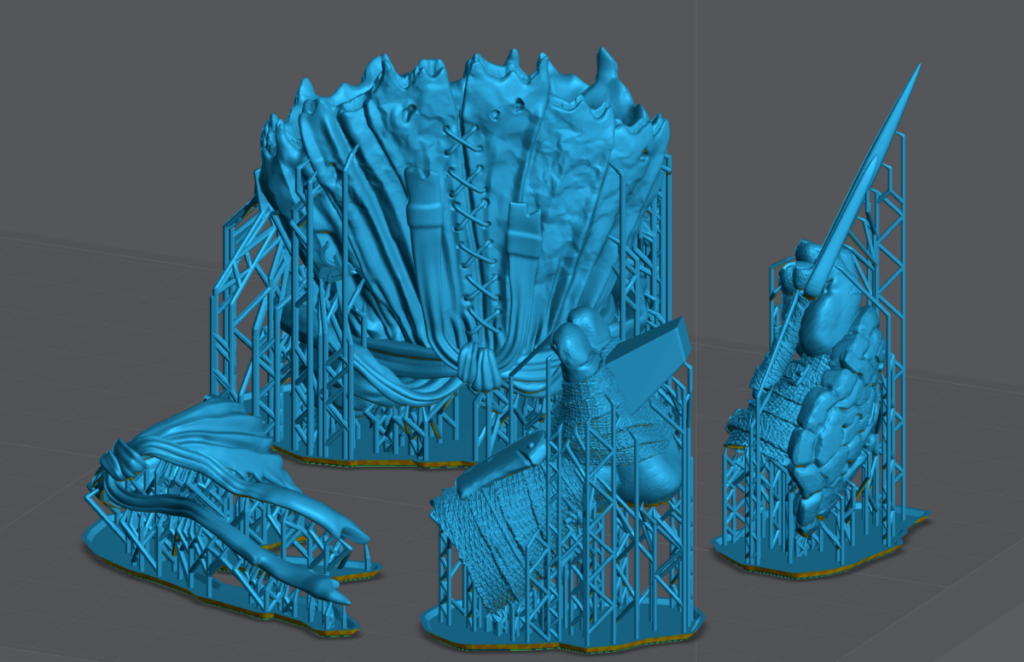
Traditional supporting vs Skyscraper Methods.
On the example below, supports will be on the exterior and final details of the model. As you can see there are supports on; back of the foot, blades and hand shield. The kilt and mask will have support damage facing up towards the viewer when assembled.
This is an example of what not to do.
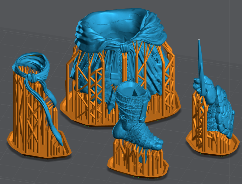
Example of my Skyscraper method: (Objects are facing up like a skyscraper to build on top of itself. Hollowing is used to reduce cross sections.)
Supports are under folds that will point down in the completed mode and/or inside joints (the best place) that will be glued.
Example of Skyscraper Orientation method – More examples found in the “Supporting” chapter
More examples found in the “Supporting” chapter
0.01mm tolerances
For some objects the only way to get accuracy you need is to print them straight up, Like a skyscraper. Below are some examples of objects with .01mm tolerances.
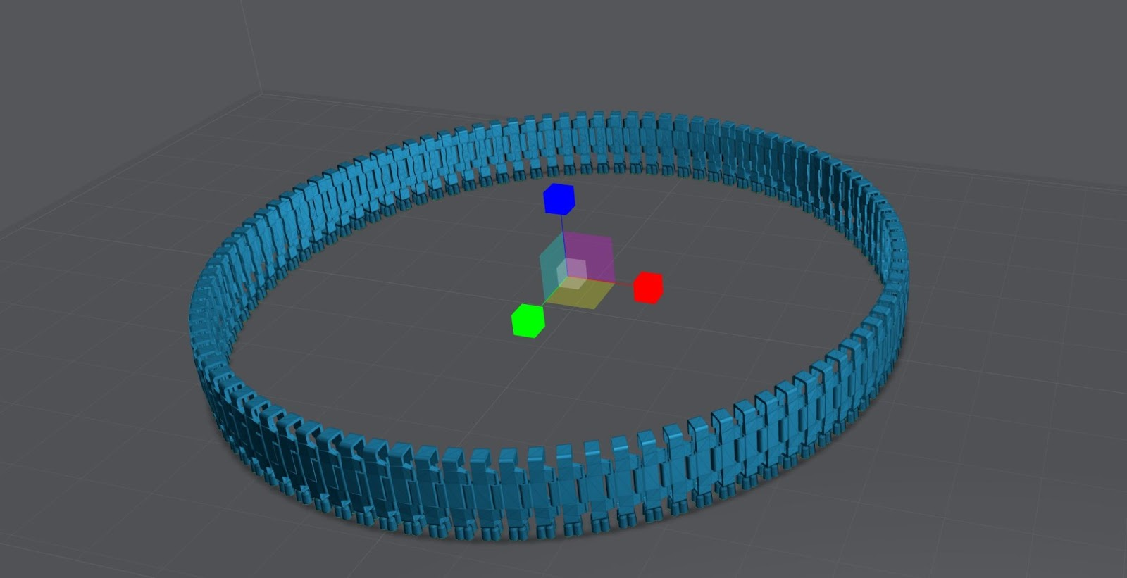
Example of many extremely low tolerance parts on a single build plate.
This moving track has over 90 links and was printed as a single part. Only possible using this Method and a very good resin. I used 100% Siraya-Tech Navy Gray.
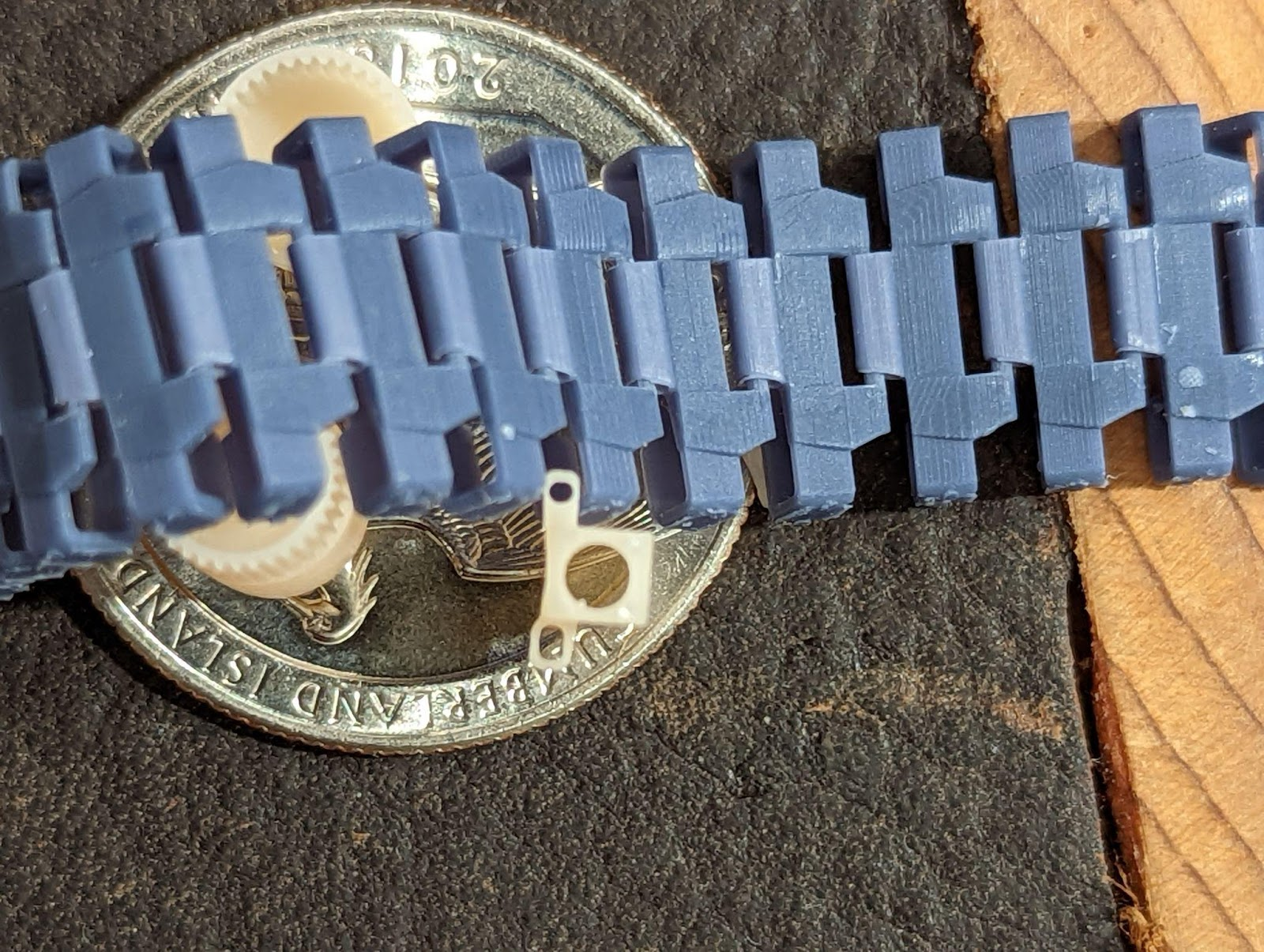
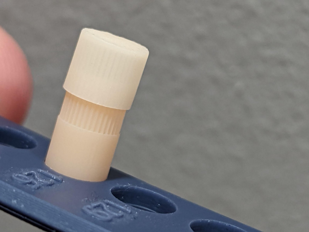
To visualize the track above I printed it as multiple parts. The size of the pin hole is 0.376mm and the pin is 0.354 mm. Thats .022mm total but I need a gap around the entire pin, that’s 0.011 tolerance! I also printed gear with a cap that has 0.008mm of tolerance.
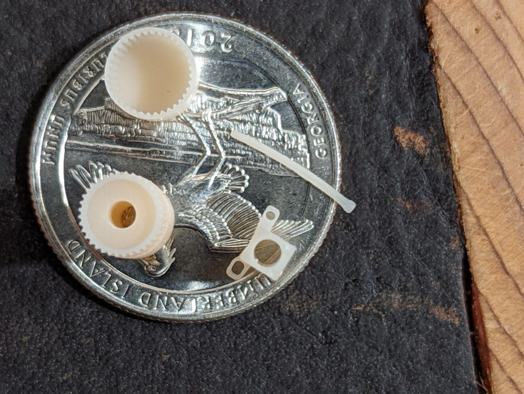
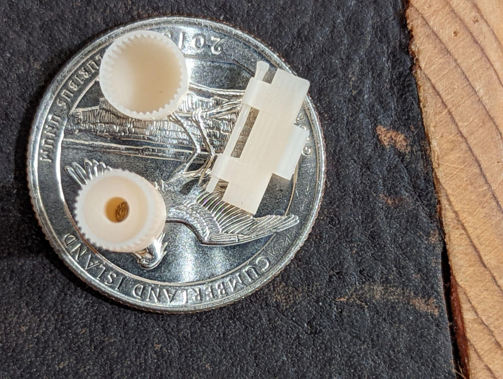
Notice the ridges compared to the ridges on a US Quarter.

For miniatures this means more detail. This also works for tall thin objects like these swords. Mulan’s sword is so thin you can still see through it. Till it was cured it would fold over like a wet noodle.Yet the final product still has amazing detail and it kept its shape.

Last updated on