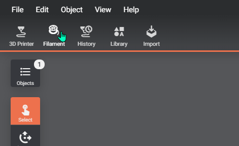
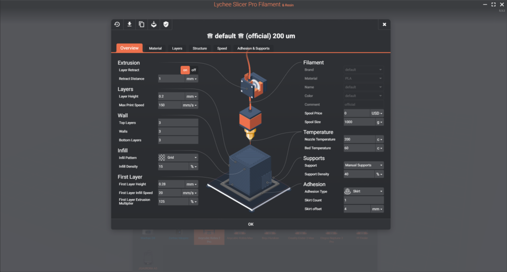
In the Toolbar, you can find the Filament menu. This menu gives you access to a variety of advanced settings that you can customise depending on the type of filament you use, your printer type, and your 3D model, to ensure the success and overall quality of your print.
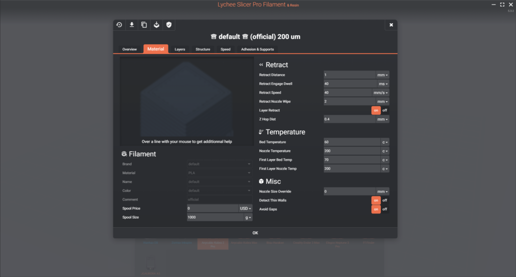
Material
Filament
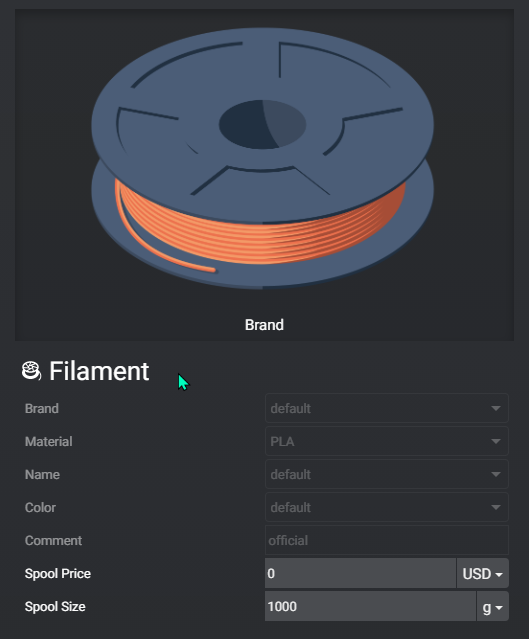
Brand: The name of the filament manufacturer
Material: The type of filament – PLA/PETG/ABS/TPU/ASA
Name: Filament range (inside the material like PLA/PLA+/PLA HD)
Colour: The colour of the filament
Comment: You can use it to personify your profile name
Spool Price: The price of one spool of filament (Classic spools weigh 1kg but you can find 500/750g spools of more “exotic” material)
Spool capacity: Allows you to indicate the weight of your spool
Impact on the print : None
Retract
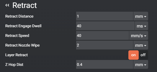
Retract Distance: Also known as retraction distance, is the length of filament that is pulled back when your nozzle or print head moves between two points. Retraction helps prevent stringing, which occurs when melted filament drips or oozes out during non-printing movements.
To mitigate this issue, you need to reduce the nozzle pressure, effectively moving the filament upward. The retract distance you should use depends on your extruder type. For direct drive extruders, the value is around 1mm, while for Bowden extruders, it’s around 4mm.
Retract Engage Dwell: After retracting the filament, the printer often performs a series of movements before continuing with the print. During this time, a wait or timeout period is introduced to ensure that the retraction process is completed and that the filament has moved properly.
This timeout period allows for a pause before resuming printing, to prevent any issues caused by incomplete retraction or filament buildup. The specific duration of the timeout can vary depending on your printer settings and can be adjusted to suit your needs.
Retract Speed: This parameter determines the speed at which the filament is retracted (pulled back) and advanced (pushed down). The typical speed for this operation is around 35-40mm/s.
Retract Nozzle Wipe: Even with optimal settings for Retract Distance and Retract Speed, stringing can still occur during the retraction between two points. To address this issue, the nozzle can be wiped on the previous path it printed to remove any residual filament. The length specified in Retract Nozzle Wipe is the distance the nozzle travels to clean itself before moving on to the next point.
Layer Retract: This option allows you to activate or deactivate retraction before moving to the next layer. Normally, retraction occurs during XY travels, but enabling this feature extends it to also include a retraction before changing layers or Z height. This can be helpful when your Z seam isn’t aligned, and you want to prevent stringing between these two points.
Z Hop Dist: Raising the Z-axis slightly with a retraction has several advantages.
Firstly, it helps limit stringing. Even with appropriate retraction settings, some residual stringing may occur, and Z Hop Dist reduces this effect along the Z-axis without affecting the X and Y-axes.
Secondly, Z Hop Dist is useful when there are multiple objects on the print bed, as it helps avoid collisions with other objects.
Lastly, the Z Hop Dist is beneficial for models with overhangs. It prevents collisions with ascending overhang points.
Impact on the print: Visual (stringing)
Temperature
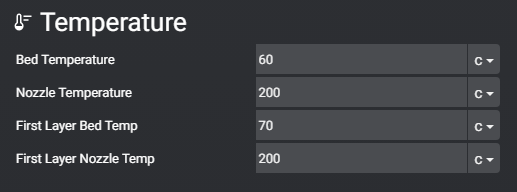
Bed Temperature: This refers to the temperature of the print bed. The required bed temperature depends on the type of filament being used for the print.
As a rule of thumb, the bed temperature should be close to the glass transition temperature of the filament. The glass transition temperature is the point at which the filament transitions from a solid to a partially melted state, making it pliable for shaping.
Bed emperature examples: PLA at around 60°C, PETG at around 80°C, ABS/ASA at around 100°C, and TPU/TPE at around 50°C.
Nozzle Temperature: This is the temperature of the printer’s nozzle or heat block. The filament starts in a solid state and needs to be heated to a specific temperature to become molten and ready for printing. The required nozzle temperature varies depending on the type of filament used.
For materials like PLA, PETG, and ABS/ASA, adjusting the nozzle temperature can impact the material’s rigidity. Lower temperatures can result in less stringing and improved overhang performance. TPU filament, being flexible, can be influenced in terms of rigidity and interlayer adhesion by adjusting nozzle temperature.
Nozzle temperature examples: PLA at around 200°C, PETG at around 230°C, ABS/ASA at around 240°C, and TPU at around 220°C.
First Layer Bed Temp: Slightly increasing the bed temperature (around 5°C) for the first layer can enhance adhesion between the first layer of filament and the print surface. The elevated bed temperature helps the filament reach its glass transition state more effectively, ensuring better adherence to the print surface, which can be PEI, glass, or any other compatible material.
First Layer Nozzle Temp: Slightly increasing the nozzle temperature (around 5°C) for the first layer also improves first-layer adhesion. This temperature adjustment makes the filament more fluid and allows it to conform better to the shape of the print bed.
Impact on the print: These temperature adjustments have a significant impact on print quality, influencing factors such as adhesion to the build plate and the strength of the printed part.
Misc
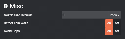
Nozzle Size Override: The default nozzle size tends to be 0.4mm. However, users may want to override this default value to use larger or smaller line widths. Larger line widths can reduce print time, while smaller ones can enhance fine detail quality.
Detect Thin Walls: When printing, the perimeters typically have a width equal to the nozzle size. In some cases, if you’re printing thin details, it may not be possible to have an exact number of perimeters to fill the space, resulting in small gaps between walls.
The Detect Thin Walls feature helps address this issue. For example, if you’re trying to print a 1mm-wide object with a 0.4mm nozzle, you can fit 2 walls of 0.4mm each (0.4mm x 2 = 0.8mm on your 1mm object). However, there would be a 0.2mm gap (1mm – 0.8mm). To seal this gap, Lychee Slicer can add a thin wall of 0.2mm to be printed.
Avoid Gaps: This mode tries to avoid gaps or voids and minimizes the use of retraction during the print.
Impact on the print: These settings have a visual and strength impact on the printed object, ensuring that all gaps and voids in the print’s perimeters are effectively filled. This can result in a visually more appealing and a structurally sounder print.
Layers
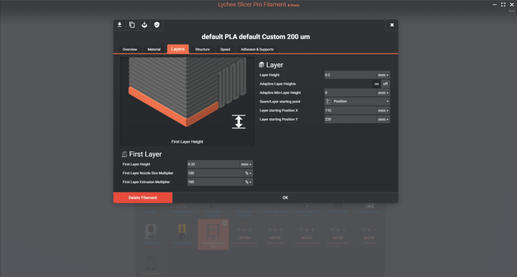
First layer
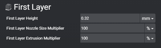
First Layer Height: This settings determines the thickness of the first layer. The first layer height is usually set slightly higher than the layer height for the rest of the print. This thicker first layer enhances adhesion to the build plate, improving the chances of the print sticking to the plate properly. While not mandatory, it is particularly useful for users experiencing bed adhesion issues.
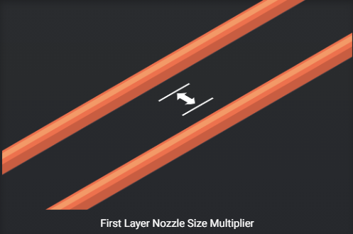
First Layer Nozzle Size Multiplier: This parameter influences the width of the open space between lines on your first layer.
First Layer Extrusion Multiplier: The first layer extrusion multiplier controls the amount of filament sent into the nozzle to fill the open spaces created by the first layer nozzle multiplier.
Impact on the print: These settings have a significant impact on your print, especially when it comes to adhesion. They play a crucial role in determining whether your print will stick to the build plate or fail (ex: spaghetti-like mess on the print bed).
Layer
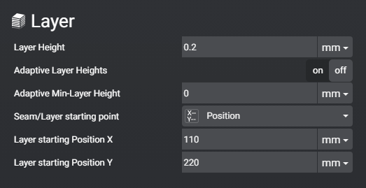
Layer Height: It determines the thickness of each layer in your print. A greater layer height results in faster prints but may lead to more visible layers in the final object.
Conversely, thinner layers yield slower prints but produce less noticeable or virtually invisible layer lines. Thinner layers are particularly beneficial for models with overhangs since they reduce the space between the layers, making overhangs smoother and more structurally sound.
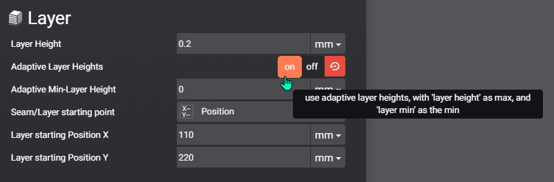
Adaptive Layer Heights: Enabling adaptive layer heights allows the slicer to adjust layer thickness based on the geometry of the object being printed. For straight sections, thicker layers are used, while thinner layers are applied to curves and overhangs.
Adaptive Min-Layer Height: This sets the minimum thickness for layers during adaptive layer height adjustments, creating a range between the minimum and maximum layer height.
Seam/Layer Starting Point: This parameter controls the position of the Z seam, which is where the nozzle begins or ends a layer.
picture here*
Since the nozzle does not print in a continuous spiral but rather as a series of non-continuous circles, the starting point of each layer can have a noticeable impact on the final print. The available options are:
- Last: The Z seam will be at the end of the layer. The specific position may vary.
- Center: The seam will be placed at the center of the object.
- Origin: The starting point aligns with the origin of the bed, typically at coordinates (0,0).
- Random: The seam is randomly placed on your print.
- Position: This option allows you to specify a fixed position for the Z seam using the two parameters under. (Layer Starting Position X and Layer Starting Position Y)
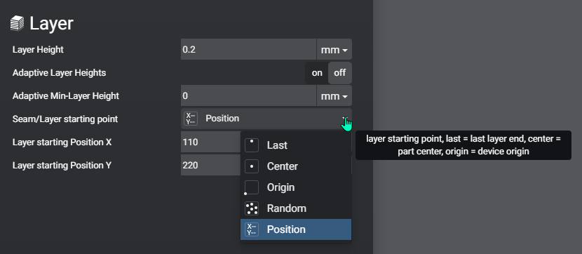
Layer Starting Position X: Sets the X-position of the Z seam along the red axis.
Layer Starting Position Y: Sets the Y-position of the Z seam along the green axis.
Impact on the print: These settings primarily impact the visual quality of the print, with thinner layers resulting in less visible layer lines and improved overhangs. The Z seam’s position can affect the appearance of the print’s surface.
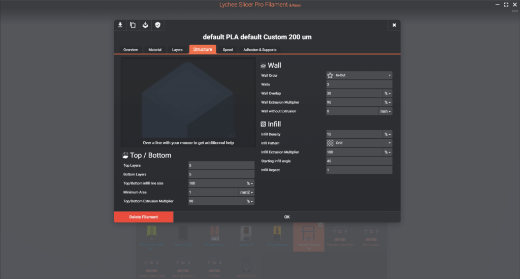
Structure
Top / Bottom
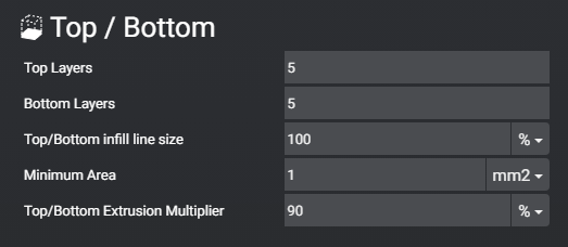
Top Layers: determines the number of layers at the top of your print.
Adding more top layers increases the strength and solidity of the top surface of the object. If you choose to have fewer top layers, the top surface will be thinner, and the infill may become visible.
Setting the number of top layers to 0 results in no top layers, is useful for specific objects like vases, pencil holders, or when you want the infill pattern to be visible.
Bottom Layers: determines the number of layers at the bottom of the print.
It can refer to the part of the object in contact with the build plate (including the first layer), or simply the number of solid layers at the bottom.
Increasing the number of bottom layers enhances the strength and stability of the object’s base. Setting the number of bottom layers to 0 exposes the infill at the bottom of the object.
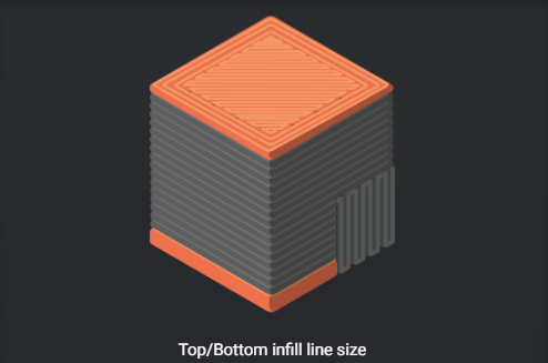
Top/Bottom Infill Line Size: This parameter specifies the width of the free space between lines in the top and bottom layers. It does not impact the first layer settings when the bottom is in direct contact with the build plate.
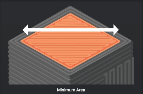
Minimum Area: This setting defines the minimum surface area to be solid and not just a perimeter. Increasing this value will eliminate solid infill from your print. Solid infill consists of both the top and any internal solid layers.
Fill Extrusion Multiplier: This value determines the amount of filament extruded to fill in the free space within the top and bottom infill line size.
Impact on the print: These settings primarily influence the strength of the print by adding more solid layers near the top and bottom. They can also affect the visual appearance of the object, as insufficient top and bottom layers may reveal the underlying infill pattern.
Wall
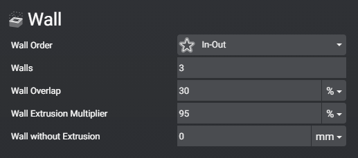
Wall Order: This setting determines the order in which perimeters are printed, either external first or internal first.
The default choice for most users is “In-Out”, which results in better overhangs. However, “Out-In” is an alternative option chosen by a small percentage of users for specific reasons:
- VFA (Vertical Fine Artifacts): To avoid wood patterns on the external surface of the print and to ignore vertical fine artefacts.
- Dimensional Accuracy: Printing the external perimeter first allows any potential over-extrusion to impact the internal side of the print rather than the external surface.
Walls: This setting specifies the number of perimeters printed around the object. More walls result in a stronger and thicker outer shell.
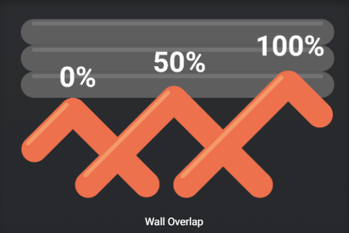
Wall Overlap: The filament extruded from the nozzle has a cylindrical shape.
If two adjacent cylinders are printed with no overlap, there will be a small gap at the top and bottom of the meeting point between these two cylinders.
To ensure they are fully joined and the print remains intact, the overlap parameter determines how much of the perimeter will be printed over the infill.
The amount of overlap can depend on the nozzle diameter (consider adapting it to the wall thickness rather than nozzle size). For instance, a 30% shell overlap (with a 0.4mm nozzle) means there’s 0.12mm of contact between wall and infill.
Wall Extrusion Multiplier: This value dictates the amount of filament extruded to print the wall perimeters.
Wall without Extrusion: During printing, the nozzle experiences high pressure as it pushes filament through. To move to the next point, the nozzle must retract and reduce pressure to prevent stringing. However, this may not always be sufficient to prevent oozing. To facilitate this pressure reduction, you can enable “Shell coast” at the end of each line. This feature does not actively push filament through the nozzle at the line’s end, and the length of non-extrusion is defined by this parameter. It allows gravity to slowly push filament into the nozzle so that when you retract before moving to the next point, the nozzle’s pressure is minimal, preventing oozing or stringing in your print.
Impact on the print: These settings primarily influence the strength and thickness of the object’s side (more walls make it thicker). They also affect the visual appearance of the object and help prevent oozing or stringing.
Infill
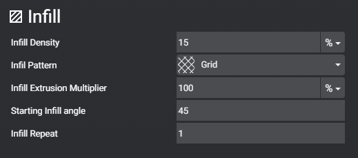
Infill Density: This setting determines the volume of infill material within your object. Infill is not visible unless the top, bottom, or wall layers are removed. Increasing infill density adds more solidity to your object, but it also increases the printing time.
Infill Pattern: This setting defines the shape of the infill inside your object. It doesn’t affect the visual appearance unless the top, bottom, or walls are removed. There are several infill patterns to choose from, each with unique properties:
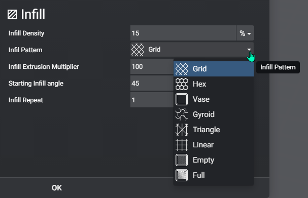
- Grid: The infill is shaped like a wire grid.
- Hex: Infill forms a honeycomb pattern.
- Vase: There is no infill, only perimeters. There are typically no z-seams either.
- Gyroid: Infill has a 3D undulating shape.
- Triangle: Infill is arranged in a triangular pattern.
- Linear: Infill consists of lines that cross every other layer.
- Empty: There is no infill, only walls.
- Full: Infill is replaced by solid layers. You can adjust this by modifying the top/bottom setting.
Infill Extrusion Multiplier: This parameter controls the flow of the infill material, but it does not affect the width of the infill. It may need clarification or adjustment to specify its effect on width.
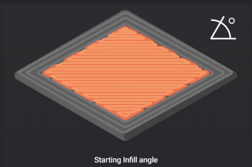
Starting Infill Angle: You can choose whether the infill pattern is solid and parallel with the wall (0 degrees) or if it crosses the wall (e.g., 45 degrees). This setting can be used for aesthetic purposes, especially when there are no top layers, and you want the infill to match the wall direction.
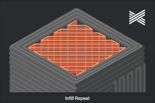
Infill Repeat (Only Works with Linear Infill): This setting determines the number of lines oriented in the same direction in the linear infill pattern. For example, if you have linear infill, you can specify that lines should alternate, with one line on top of the other. The orientation of these lines can vary between 0 and 90 degrees.
Impact on the print: Infill density directly affects the strength of your object. You can use lower infill percentages (around 5-10%) for visual objects like decorations or busts, and higher percentages (around 30-40%) for mechanical parts. The choice of infill pattern can also have a minimal visual impact on your print.
Speed
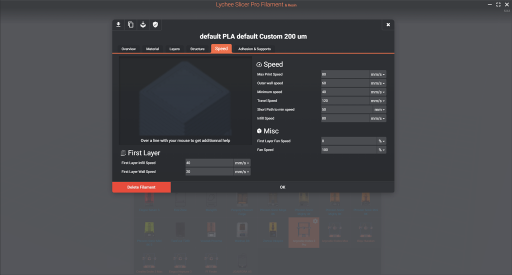
First layer
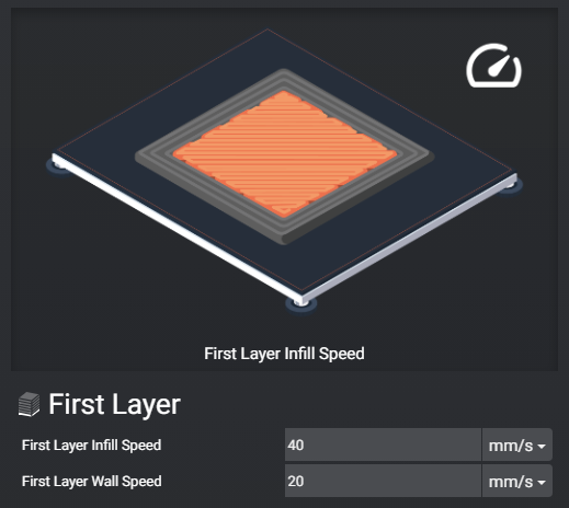
First Layer Infill Speed: This setting controls the speed at which the infill or solid portions of the first layer are printed.
The first layer is crucial as it adheres to the build plate and provides a strong foundation for the rest of the print. Printing the first layer at a lower speed ensures better adhesion and stability.
A recommended range is 20-40mm/s for infill speed on the first layer.
First Layer Wall Speed: This parameter determines the speed of printing the perimeters of the first layer. Just like with infill speed, a slower wall speed is essential for the first layer to ensure proper adhesion to the build plate and accurate print details.
A typical range for first layer wall speed is 10-20mm/s, which is suitable for most 3D printers.
Impact on the print: These settings are critical for the success of your 3D print. Achieving a strong bond between the first layer and the build plate is essential for overall print quality. Using the recommended speeds ensures that the first layer adheres well and is printed accurately.
Speed
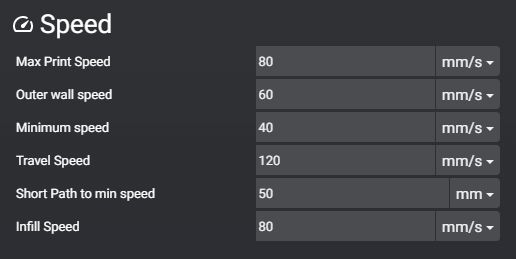
Max Print Speed: This setting determines the maximum speed at which printing moves are executed. It’s primarily used for inner walls and the solid sections of your 3D print.
Outer Wall Speed: The outer wall speed sets the speed at which perimeters or the outer shell of your object are printed. Slower speeds are often preferred for outer walls to achieve a better external appearance.
Minimum Speed: This is the speed used for short movements with little extrusion. Slowing down the speed for short paths can improve the overall print quality, especially for fine details.
Travel Speed: Travel speed defines the maximum speed for non-printing moves, which occur when the nozzle is moving between two printing locations. Travel speeds are usually higher than printing speeds to allow for swift movement without printing.
Short Path to Min Speed: If a printed path is shorter than the value set here, it will be printed at the minimum speed. This ensures that very short movements are executed accurately.
Infill Speed: Infill speed determines how fast the infill is printed. Since infill is typically not visible in the final print, it can be printed more quickly than other sections. You can set it to 0 to use the maximum print speed.
Impact on the print: These speed settings play a crucial role in the success of your 3D print. If the speed is too high, it can lead to under-extrusion issues, where the hotend can’t melt filament fast enough to keep up with the speed. Slower speeds are often essential for achieving the desired print quality, especially for outer walls, topmost layers, and fine details.
Misc
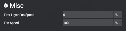
First Layer Fan Speed: This setting controls the fan used for cooling during the first layer of your print.
Fan Speed: Filament needs cooling to transition from a molten state to a solid one. The speed at which cooling is applied affects the print’s overhang capabilities.
Faster cooling allows for better overhangs, but it can reduce the overall strength of the object.
The appropriate fan speed depends on the type of filament you’re using. For instance, PLA typically requires around 100% fan speed, while PETG works well with speeds between 60-70%, and ABS/ASA may need much lower speeds, around 0-30% (without enclosure).
Impact on the print: The fan speed is essential for achieving the right balance between overhang performance and print strength. The optimal fan speed varies based on the filament type being used.
Adhesion & Supports
Brim
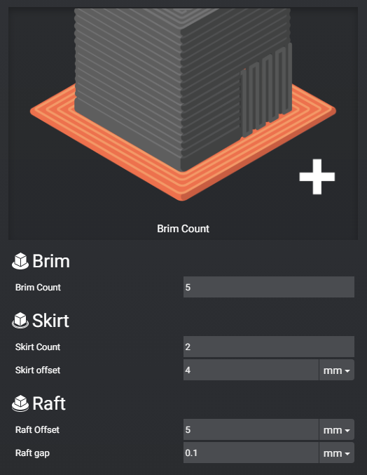
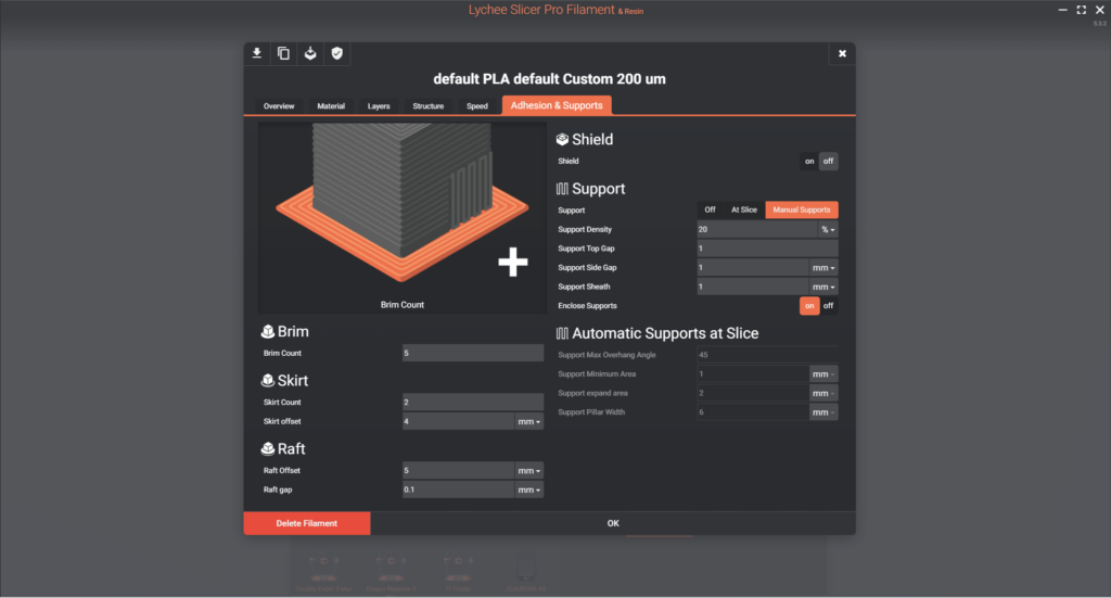
Brim Count: This setting determines the number of lines added to the perimeter of your print to enhance adhesion to the print bed. It increases the surface area of the object in contact with the bed. Brims are particularly useful for smaller objects, articulated models, and prints where bed adhesion might be challenging.
Impact on the print: Adding a brim improves adhesion to the print bed by increasing the contact surface, making it especially helpful for prints that might otherwise have trouble sticking to the bed.
Skirt
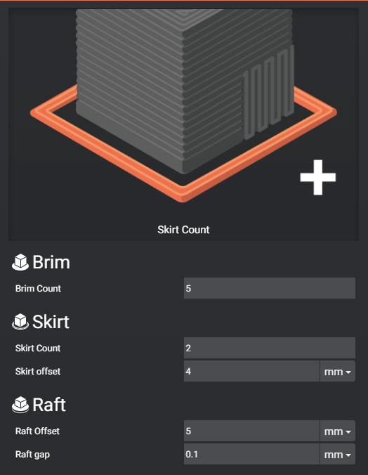
Skirt Count: This setting determines the number of lines in the skirt around your object. The skirt serves multiple purposes, such as allowing you to quickly inspect the first layer (a well-attached skirt suggests your print is likely to adhere well too) and purging or ensuring good pressure in your nozzle before the actual print begins.
Skirt Offset: The skirt offset refers to the distance between your object and the skirt. Typically, this offset is set to around 3-4mm. However, you can also use it as a brim with a quick release system. In this case, you set a smaller offset, such as 0.1-0.2mm, so that your skirt touches your object’s perimeter but is not directly joined with it.
Impact on the print: The skirt helps you quickly inspect the quality of your first layer. It also serves as **a priming mechanism for your nozzle, ensuring that the filament is properly flowing before the main print begins.
Raft
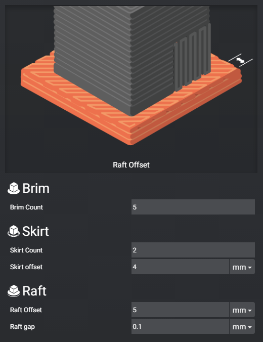
Raft Offset: The raft offset determines the additional surface area of the raft compared to the print. An offset of 0 means that the raft is the same size as your object. However, it’s usually a good idea to have a little extra surface area to make it easier to remove the raft once the print is complete.
Raft Gap: The raft gap is the air gap or vertical distance between your raft and your object. This gap ensures that the raft doesn’t fuse with your object, allowing for easier removal. A typical value for the raft gap is around 0.1-0.15mm for most materials. However, some stickier materials like PETG may require a slightly larger gap.
Impact on the print: Rafts are used to compensate for an uneven or non-flat bed and aid in bed adhesion. The settings for raft offset and gap affect how well the raft adheres to the build plate and how easy it is to remove after printing.
Shield
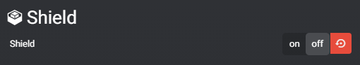
Shield: A shield is used to protect certain materials, such as ABS or ASA, from the cooling effects of airflow during printing. These materials are prone to cracking or warping if they are exposed to drafts or cold air. The shield creates a controlled environment around the print to maintain a stable temperature and prevent these issues.
Impact on the print: This feature is mainly useful for users with open or unenclosed printers who need to print technical materials that are sensitive to temperature changes. It helps ensure the successful printing of such materials by providing a stable printing environment.
Support
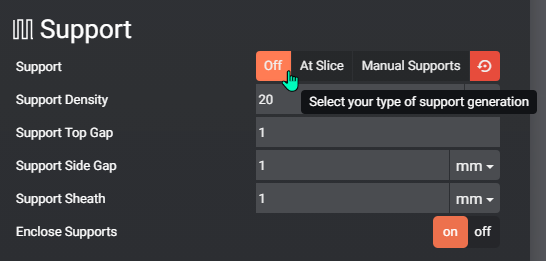
Off
No supports
Manual Supports (manual support and generate automatic supports in Prepare)
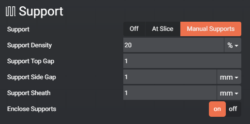
Support Density: This setting determines the density of the “infill” inside the support structures. Denser supports are stronger but require more filament and time to print. Besides, note that they might also be more challenging to remove.
Support Top Gap: This setting defines the height of the air gap between the support and the object, measured in the number of layers. For example, if you have a layer height of 0.2mm and set the top gap to 2 layers, it creates a 0.4mm air gap.
Support Offset from Part: Similar to Support Top Gap but for the XY axis. It determines the distance between your print and the support structures in the horizontal plane. Typically, a starting point of 0.8mm to 1mm is recommended. If it’s too close, the support may merge with your object, and if it’s too far, the support might not effectively support your overhangs.
Support Grow: This feature allows you to extend the support structures beyond the build plate to improve bed adhesion. Usually, an extension of 1mm to 2mm is sufficient, but for very small supports, you might increase it to 5mm or 10mm.
Support Outline: Adding a perimeter around your support structures can reinforce them, making them more stable.
Impact on the print: These settings affect the strength and stability of your support structures. A denser support can provide better support for overhangs but may be more challenging to remove. Adjusting the top gap, offset, grow, and outline can help tailor your supports to the specific needs of your print.
At Slice
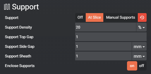
Auto support when slicing using the Automatic Supports at Slice parameters. (below)
Automatic Supports at Slice
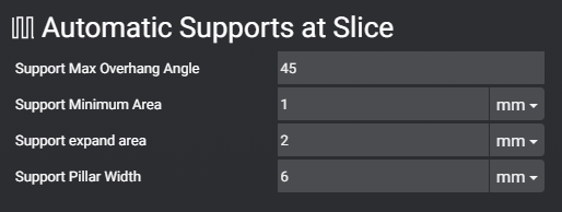
Support Max Overhang Angle: Angle at which the slicer will switch between no support needed to support needed (i.e. below this value: no support, above this value: support needed to be printed). It is around 45-55 for most printers, the better the cooling system of the head is, the more overhang you can print without issues.
Support Minimum Area: provides the minimal surface for supports to be created
Support expand area: Outgrow support on your build plate (versus your object) to achieve better bed adhesion. Usually around 1-2 mm but you can go for 5-10 if your support is really small and come off the bed.
Support pillar width: Width of the pillar composing the support. A small value means narrow pillars independent of each other, larger ones will create a network of pillars (connected one to another).
First Layer Infill Speed: This setting controls the speed at which the infill or solid portions of the first layer are printed. The first layer is crucial as it adheres to the build plate and provides a strong foundation for the rest of the print. Printing the first layer at a lower speed ensures better adhesion and stability. A recommended range is 20-40mm/s for infill speed on the first layer.
First Layer Wall Speed: This parameter determines the speed of printing the perimeters of the first layer. Just like with infill speed, a slower wall speed is essential for the first layer to ensure proper adhesion to the build plate and accurate print details. A typical range for first layer wall speed is 10-20mm/s, which is suitable for most 3D printers.
Impact on the print: These settings are critical for the success of your 3D print. Achieving a strong bond between the first layer and the build plate is essential for overall print quality. Using the recommended speeds ensures that the first layer adheres well and is printed accurately.
Last updated on